Experience Center
Configuring a Branch Configuration Template
The Branch Connector Configuration Template provides configuration information for virtual and physical branch devices. The configuration URL is required for deploying virtual and physical branch devices. For virtual branch devices, the administrator provides the configuration URL to the virtual device. For physical branch devices, the configuration URL is retrieved by the Zero Touch Provisioning process.
For Branch Connectors to function in high availability, configure each Branch Connector with separate configuration templates with the same Location Name and Branch Connector Group Name.
To add a Branch Connector Configuration Template:
- Go to Infrastructure > Connectors > Edge > Management > Appliances > Add.
- Click Add Branch Connector Configuration Template.
- On the Add Branch Connector Configuration Template page, decide whether to deploy a hypervisor host or a hardware device:
- Hypervisor Host
- On the General Information tab:
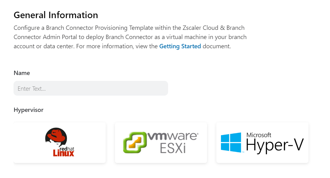
- Name: Enter a name for your provisioning template.
Hypervisor: Select either Red Hat Linux, VMware ESXi, or Microsoft Hyper-V as your hypervisor host.
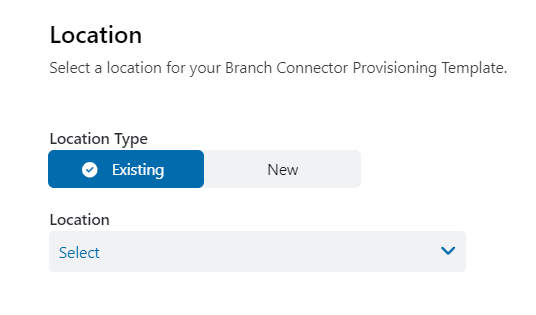
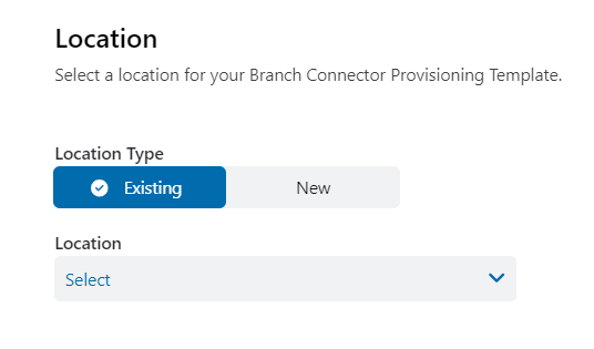
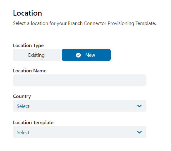
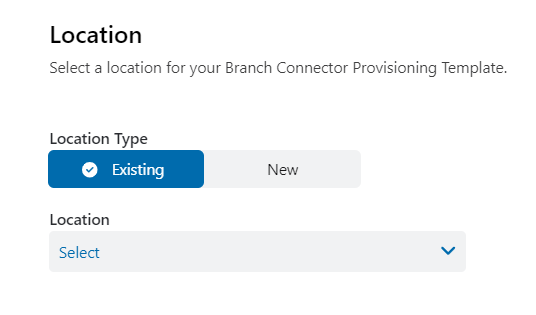
On the Location tab, select an Existing or New location.
This location is created in Internet & SaaS. You can use the location as a policy parameter in Internet & SaaS, Private Applications, and the Admin Portal.
If you select an Existing location, from the Location drop-down menu, select a location.
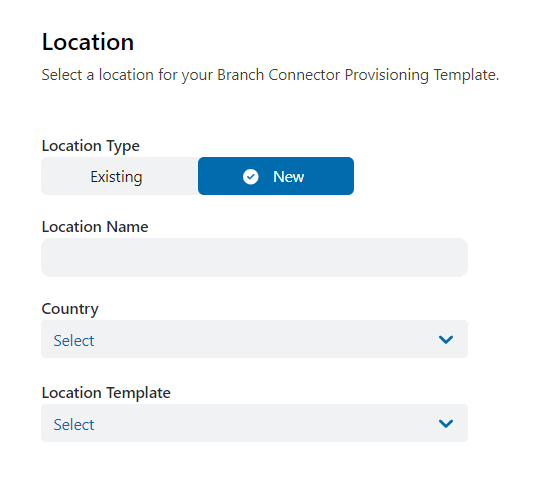
- If you select a New location:
- Location Name: Enter a name for your new location.
- Country: From the drop-down menu, select the country.
Location Template: From the drop-down menu, select a location template based on your requirements.
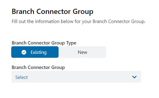
- On the Branch Connector Group tab, select an Existing or New group. Branch Connector groups enable you to apply policies to a group of deployed Branch Connectors, upgrade Branch Connectors belonging to a group to maintain redundancy while upgrades are being executed, and share Private Applications synthetic IP address resolutions among the group members.
If you select an Existing group, then select an existing Branch Connector group from the drop-down menu.
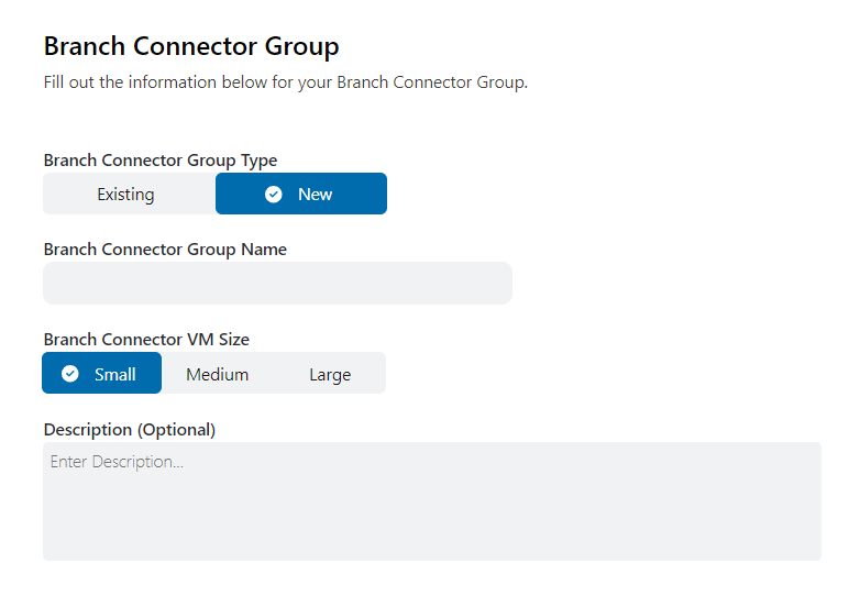
- If you select a New group:
- Branch Connector Group Name: Enter a name for your Branch Connector group.
- Branch Connector VM Size: Select from Small or Medium. If you select Medium, High Availability Deployment is automatically enabled.
Description: (Optional) Enter additional information about the Branch Connector group.
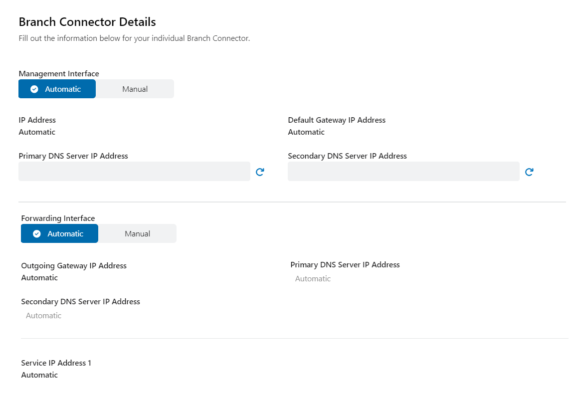
On the Branch Connector Details tab, select Automatic or Manual. Medium Branch Connector VM sizes require Manual settings in the Forwarding Interface field to enable high availability. If Automatic is selected, all fields are displayed automatically. If you select Manual, in the following sections:
- Management Interface
Use the Management Interface section to configure the Branch Connector's network interface and operations.
- IP Address: Enter the IP address of the Branch Connector.
- Default Gateway IP Address: Enter the default gateway IP address of the Branch Connector.
- Primary DNS Server IP Address: Enter the IP address of the primary DNS server. This is one of the two DNS servers used for load balancing.
- Secondary DNS Server IP Address: Enter the IP address of the secondary DNS server. This is one of the two DNS servers used for load balancing.
- Forwarding Interface
Use the Forwarding Interface section to configure the Branch Connector's selected forwarding destinations.
If you select the Medium Branch Connector VM size, High Availability Deployment is automatically enabled, and you cannot disable it.
- High Availability Deployment: Select Enabled or Disabled. If you select Enabled, two Branch Connectors share a virtual IP address on their forwarding interfaces in active or standby mode. Traffic sent to the shared virtual IP address reaches the active Branch Connector. If the primary Branch Connector stops responding, the traffic automatically fails over to the second Branch Connector.
If High Availability Deployment is disabled:
- Primary DNS Server IP Address: Enter the IP address of the primary DNS server.
- Secondary DNS Server IP Address: Enter the IP address of the secondary DNS server.
- Outgoing Gateway IP Address: Enter the default gateway IP address.
- Service IP Address 1: Enter the primary service IP address.
If High Availability Deployment is enabled:
- Primary DNS Server IP Address: Enter the IP address of the primary DNS server.
- Secondary DNS Server IP Address: Enter the IP address of the secondary DNS server.
- Outgoing Gateway IP Address: Enter the default gateway IP address.
- Service IP Address 1: Enter the primary service IP address.
- Service IP Address 2: Enter the secondary service IP address.
- Load Balancer IP Address: Enter the load balancer IP address.
- Virtual IP Address: Enter a valid virtual IP address that the two Branch Connectors in a high availability pair share. For the Branch Connectors to access the same default gateway, the virtual IP address must be on the same broadcast domain as the forwarding interface.
- Management Interface
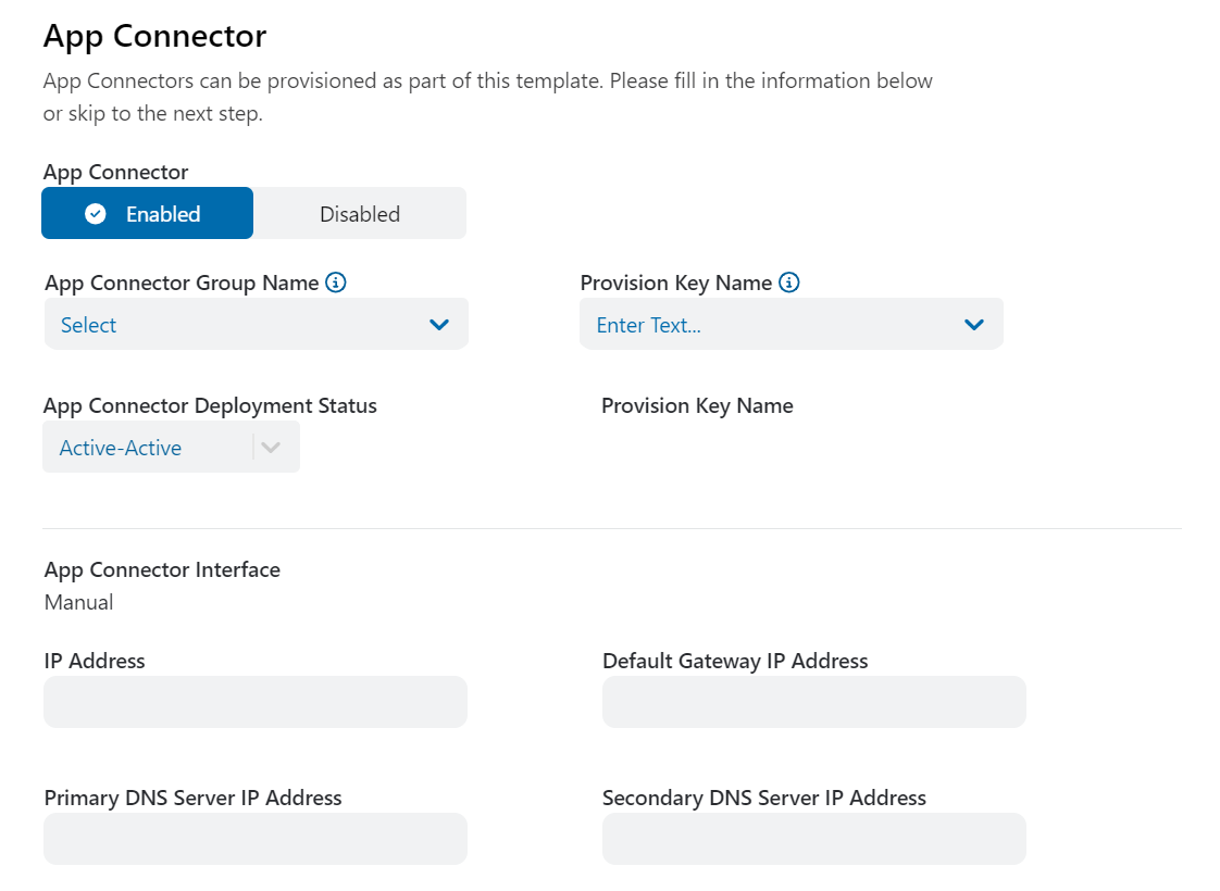
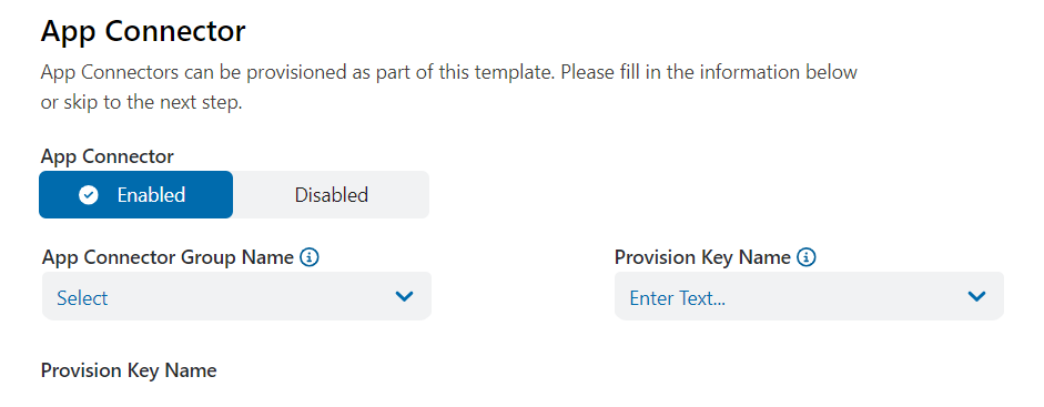
- On the App Connector tab, select Enabled or Disabled. If you enable App Connectors:
- App Connector Group Name: Select your desired App Connector group name.
- Provision Key Name: Select your desired provisioning key name.
- App Connector Deployment Status: This field displays the App Connector deployment status.
App Connector Interface: This field is automatically set to Manual.
- IP Address: Enter the IP address of the App Connector.
- Default Gateway IP Address: Enter the default gateway IP address of the App Connector.
- Primary DNS Server IP Address: Enter the IP address of the primary DNS server. This is one of the two DNS servers used for load balancing.
- Secondary DNS Server IP Address: Enter the IP address of the secondary DNS server. This is one of the two DNS servers used for load balancing.
- On the Review tab, review the values and settings you entered.
- On the General Information tab:
- Hardware Device
- On the General Information tab:
- Name: Enter a name for the Branch Connector Configuration Template.
- Hardware Device: Select ZT400, ZT600, or ZT800 as your hardware device.
- Deploy as Gateway: To deploy the Zero Trust Branch Device in gateway mode, select Yes. To not deploy the Zero Trust Branch Device in gateway mode, select No. Gateway mode is only supported on hardware devices.
Close- Gateway Mode
In gateway mode, the Zero Trust Branch Device enables direct, secure access from your private network to other geographically distributed parts of your private network, cloud applications, and the internet over one or more internet service provider (ISP) connections. It can also dynamically determine the best quality link, forward specific traffic toward that link, and function as a local router. Local devices can communicate without an external router. In brownfield deployments, you can also deploy the hardware device in gateway mode inside your network while an existing device connects you to the internet.
- On the Location tab, select an Existing or New location.
If you select an Existing location, from the Location drop-down menu, select a location.
- If you select a New location:
- Location Name: Enter a name for your new location.
- Country: From the drop-down menu, select the country.
Location Template: From the drop-down menu, select a location template based on your requirements.
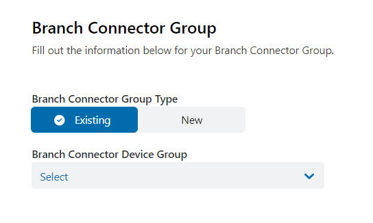
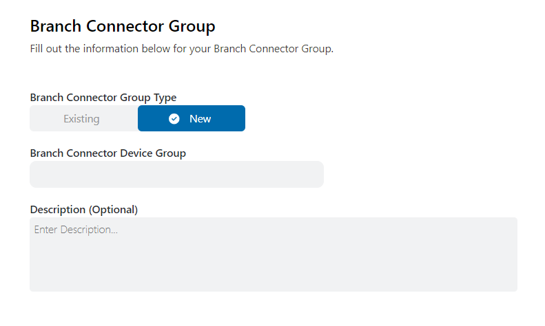
- On the Branch Connector Group Details tab, select Existing or New.
- If you select Existing, select an existing Branch Connector device group from the drop-down menu.
- If you select New:
- Branch Connector Device Group: Enter a name for your Branch Connector device group.
Description (Optional): Enter additional information about the Branch Connector device group.
- If you select Existing, select an existing Branch Connector device group from the drop-down menu.
On the Device Details tab, configure the following:
- System Settings
- In the Device Model section:
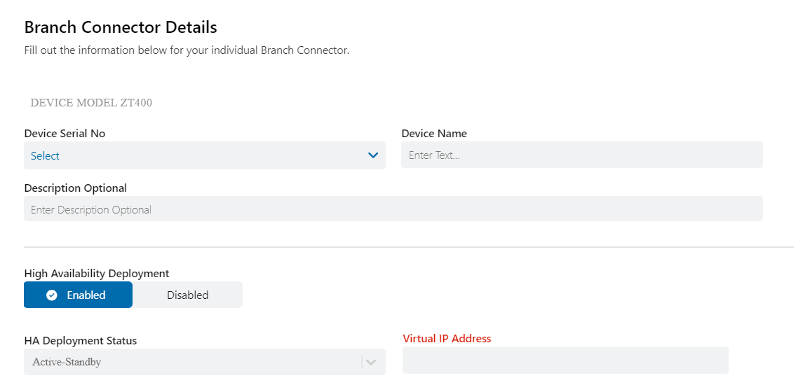
- Device Serial No: From the drop-down menu, select the device's serial number. The drop-down menu only shows devices associated with your organization and for the specified platform type.
- Device Name: Enter a name for the hardware device.
Description Optional: Enter additional information about the hardware device.
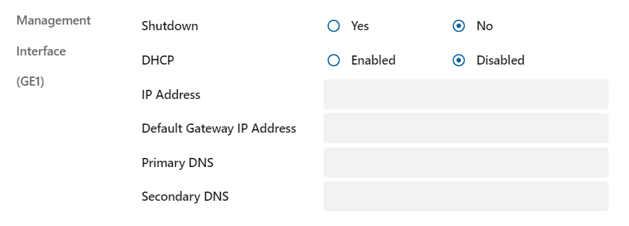
In the Management Interface section:
The management interface is set based on the hardware device selected, and you cannot change it. GE1 is set for ZT400 and ZT600. GE3 is set for ZT800.
- Shutdown: Select Yes or No. The management interface provides out-of-band access to your Zero Trust Branch Device and is enabled by default. Exercise caution when shutting down the management interface and ensure that there is an alternate method of accessing and managing the device.
DHCP: By default, the management interface is Enabled and set to receive its IP address by the Dynamic Host Configuration Protocol (DHCP) client. If you select Disabled, you can assign static IP address, gateway, and DNS configurations:
- IP Address: Enter the IP address.
- Default Gateway IP Address: Enter the default gateway IP address.
- Primary DNS: Enter the IP address of the primary DNS server.
- Secondary DNS: Enter the IP address of the secondary DNS server.
If the DHCP client is enabled on the Management Interface and it does not receive a DHCP offer, the IP address automatically defaults to 192.168.1.1/24.
- In the Device Model section:
- WAN
The wide area network (WAN) interface is an uplink for Zero Trust Branch Devices. You must assign at least one interface or subinterface to the WAN interface. Optionally, you can assign a second interface or subinterface.
- In the Interface section:
- Name: From the drop-down menu, select an interface.
MTU: Enter the permissible IP Maximum Transmission Units (MTU) of the parent interface. The default value is 1,500 bytes.
- If you intend to configure IP information on the untagged interface, select Add IP Info. In the IP Info section, configure the following:
- Description Optional: Enter additional IP information.
- DHCP: By default, the WAN interfaces are set to receive IP addresses via DHCP. Optionally, you can override the DNS configuration received via DHCP by setting your own DNS server. Depending on whether you select Enabled or Disabled, configure the following:
- If you select Enabled:
- Primary DNS Server (Optional): Enter the IP address of the primary DNS server.
Secondary DNS Server (Optional): Enter the IP address of the secondary DNS server.
When you enable DHCP, the primary and secondary DNS server fields are optional. Setting these fields overrides any DNS received via DHCP.
- If you select Disabled:
- IP Address: Enter the IP address.
- Default Gateway IP Address: Enter the IP address of the default gateway.
- Primary DNS Server: Enter the IP address of the primary DNS server.
Secondary DNS Server: Enter the IP address of the secondary DNS server.
When DHCP is disabled, the primary and secondary DNS server fields are required.
- If you select Enabled:
Uplink Mode: Select Active or Standby. At least one WAN interface must be set to Active. You can set the other WAN interfaces to either Active or Standby. You can only configure two WAN interfaces. If you set one interface to Active and one interface to Standby, data traffic goes over the active links. When the probes detect a 100 percent loss on the current active link, failover is triggered. Zscaler also sends WAN link monitoring probes on the standby link and establishes and maintains tunnels to Internet & SaaS and Private Applications for a fast switchover during a failover from the active link. If you set both interfaces to Active, Zscaler actively monitors the health of the links and determines the best link. All WAN-bound traffic follows the traffic distribution method described in Traffic Distribution. Optionally, for specific applications, you can override the device-wide traffic distribution method using traffic forwarding rules.
- If you select Add Sub Interface, you can configure subinterfaces. Subinterfaces are tagged virtual local area network (VLAN) interfaces on the parent interface. You can add up to 10 tagged VLAN interfaces per parent interface. In the Sub Interface section, configure the following:
- VLAN ID: Enter the VLAN ID as a value from
1to4094. This is the 802.1q tag for the network. - Description Optional: Enter additional subinterface information.
MTU: The IP MTU of the subinterface. By default, this value is set to
1496. It must be set to 4 bytes less than the MTU of the parent interface.- DHCP: Depending on whether you select Enabled or Disabled, configure the following:
- If you select Enabled:
- Primary DNS Server (Optional): Enter the IP address of the primary DNS server.
Secondary DNS Server (Optional): Enter the IP address of the secondary DNS server.
- If you select Disabled:
- IP Address: Enter the IP address.
- Default Gateway IP Address: Enter the default gateway IP address.
- Primary DNS Server: Enter the IP address of the primary DNS server.
Secondary DNS Server: Enter the IP address of the secondary DNS server.
If you disable DHCP, the primary and secondary DNS server fields are required.
- If you select Enabled:
Uplink Mode: Select Active or Standby. At least one WAN interface must be set to Active. You can set the other WAN interfaces to either Active or Standby. You can only configure two WAN interfaces. If you set one interface to Active and one interface to Standby, data traffic goes over the active link at all times. When the probes detect a 100 percent loss on the current active link, failover is triggered. Zscaler also sends WAN link monitoring probes on the standby link and establishes and maintains tunnels to Internet & SaaS and Private Applications for a fast switchover during a failover from the active link. If you set both interfaces to Active, Zscaler actively monitors the health of the links and determines the best link. All WAN-bound traffic follows the traffic distribution method described in Traffic Distribution. Alternatively, for specific applications, you can override the device-wide traffic distribution method using traffic forwarding rules.
- VLAN ID: Enter the VLAN ID as a value from
Traffic Distribution: Select Balanced or Best Link. By default, this field is set to Balanced, meaning traffic is distributed across all WAN links using a flow-based distribution algorithm. If you set this field to Best Link, the traffic is forwarded over the best performing WAN link. This link is determined using probes to measure loss, latency, and jitter. This setting is only applicable when there is more than one WAN interface and/or subinterface and both interfaces are set to active and operational. Zscaler actively monitors the health of the links and uses the best link. You can set certain applications use the best link via traffic forwarding rules.
Any WAN link that is selected via traffic forwarding rules takes precedence for the matching traffic over the catch-all device-level setting of this traffic distribution.
- In the Interface section:
- LAN
When a Zero Trust Branch Device is deployed in gateway mode, you must assign at least one interface to local area network (LAN).
- In the Interface section:
- Name: From the drop-down menu, select an option.
- Shutdown: To shut down the LAN interface that brings down the physical port and all of its subinterfaces, select Yes. To disable this feature, select No.
MTU: The permissible IP MTU of the parent interface. The default value is
1500bytes.
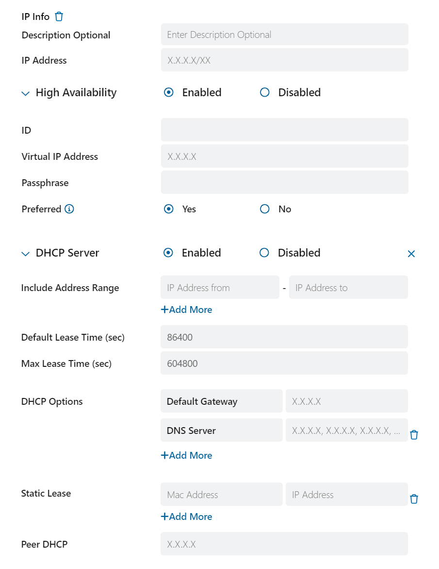
- If you intend to configure IP information on the untagged interface, click Add IP Info. In the IP Info section, configure the following:
- Description Optional: Enter a description.
- IP Address: Enter an IP address.
- High Availability: Select Disabled to disable HA or select Enabled to configure the following settings:
- ID: Enter the ID configured on the HA pair device.
- Virtual IP Address: Set the virtual IP address to belong to the same network as specified on the corresponding interface.
- Passphrase: Set the same passphrase as on the HA pair device.
- Preferred: By default, this field is set to No. If you want a specific device in the HA pair to assume the Active role when it is up, set the Preferred value on that device to Yes. Only set preferred to Yes for one of the devices in an HA pair. Setting Preferred to Yes on more than one device in an HA pair can cause unreliable behavior.
DHCP: By default, the DHCP server is Disabled. To activate the DHCP server, select Enabled and configure the following settings:
- Include Address Range: Include this range as a part of the same network specified on the interface. Include this range as a part of the same network specified on the interface. If HA is enabled, ensure that the ranges on the two devices in an HA pair match.
- Default Lease Time (sec): The default lease time is automatically set to
86400seconds, but you can change it. The maximum permissible value is3155673600seconds. - Max Lease Time (sec): The default maximum lease time is
604800seconds. The maximum permissible value is3155673600seconds. - DHCP Options: The options include the following:
- Default Gateway: Enter a valid default gateway IP address.
- DNS Server: Enter a valid DNS server IP address. You can enter up to 4 DNS server IP addresses separated by commas.
- Domain Name: Enter a valid domain name. You can enter up to 4 domain names separated by commas.
- Static Lease: Enter a MAC address and the IP assigned to a device with that MAC address. You can configure a maximum of 32 static leases per DHCP server. In HA, you must enter each static lease twice.
- Peer DHCP: Enter the peer DHCP server IP address from the other hardware device's corresponding interface. This option is configurable when HA is enabled to synchronize the DHCP leases.
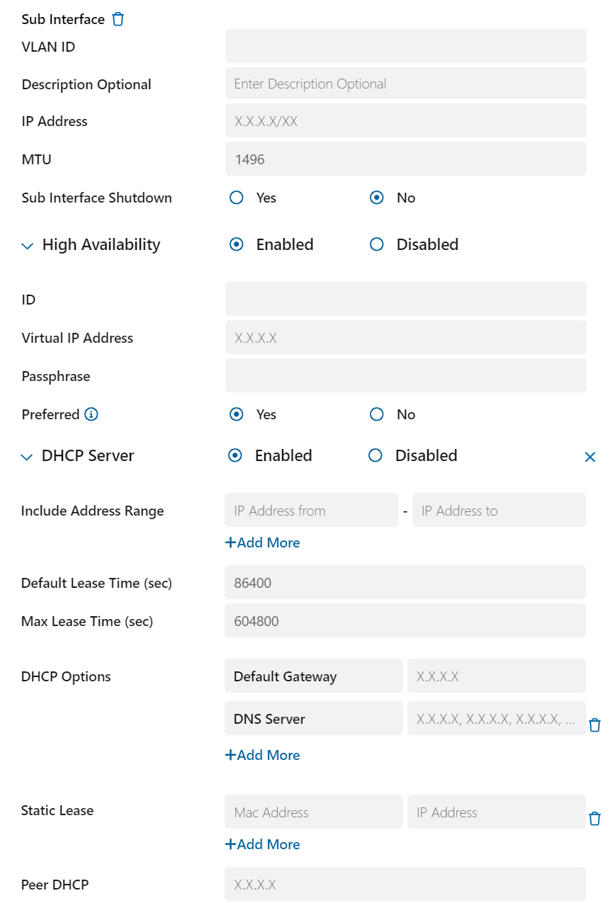
- If you select Add Sub Interface, in the Sub Interface section, configure the following:
- VLAN ID: Enter the VLAN ID as a value from 1 to
4094. This is the 802.1q tag for the network. - Description Optional: Enter additional subinterface information.
- IP Address: Enter an IP address for the subinterface.
- MTU: The permissible IP Maximum Transmission Units (MTU) of the subinterface. This is set to a default value of
1496and must be 4 bytes less than the MTU of the parent interface. - Sub Interface Shutdown: Select Yes to enable the subinterface to shut down. This only brings down the specific subinterface selected and does not affect the parent interface or any other subinterface. Select No and the subinterface does not shut down.
- High Availability: Select Disabled to disable HA or select Enabled to configure the following:
- ID: Enter the ID configured on the HA pair device.
- Virtual IP Address: Set the virtual IP address to belong to the same network as specified on the corresponding interface.
- Passphrase: Set the same passphrase as on the HA pair device.
- Preferred: By default, this field is set to No. If you want a specific device in the HA pair to assume the Active role when it is up, set the Preferred value on that device to Yes. Only set preferred to Yes for one of the devices in an HA pair. Setting Preferred to Yes on more than one device in an HA pair can cause unreliable behavior.
DHCP: Select Disabled to disable DHCP or select Enabled to configure the following:
- Include Address Range: Include this range as a part of the same network specified on the interface.
- Default Lease Time (sec): The default lease time is automatically set to
86400seconds, but you can change it. The maximum permissible value is3155673600seconds. - Max Lease Time (sec): The default maximum lease time is
604800seconds. The maximum permissible value is3155673600seconds. - DHCP Options: The options include the following:
- Default Gateway: Enter a valid default gateway IP address.
- DNS Server: Enter a valid DNS server IP address. You can enter up to 4 DNS server IP addresses separated by commas.
- Domain Name: Enter a valid domain name. You can enter up to 4 domain names separated by commas.
- Static Lease: Enter a MAC address and the IP assigned to a device with that MAC address. You can configure a maximum of 32 static leases per DHCP server. In HA, you must enter each static lease twice.
- Peer DHCP: Enter the peer DHCP server IP address from the other hardware device's corresponding interface. This option is configurable when HA is enabled to synchronize the DHCP leases.
- VLAN ID: Enter the VLAN ID as a value from 1 to
- In the DNS Server section:
Use WAN DNS Server: To use the DNS server from the WAN interfaces as the DNS server for LAN, select Yes. To provide a primary and secondary DNS server, select No. The App Connector uses the LAN DNS servers to resolve the original IP of an application at the branch. The LAN DNS servers can also be referenced in the DNS gateway object, which is then used in DNS policies. If you select No:
- Primary DNS Server: Enter the IP address of the primary DNS server.
- Secondary DNS Server: Enter the IP address of the secondary DNS server.
- In the Interface section:
- Routing
A maximum of 32 static routes are permitted. You cannot configure the default static route. The next hop of the static route is resolvable over one of the connected LAN interface and/or subinterfaces.
- Route: Set the route IP address to the prefix you want to reach.
Gateway: Enter the gateway IP address.
- System Settings
- On the App Connector tab, select Enabled or Disabled. If you enable App Connectors:
- App Connector Group Name: Select your desired App Connector group name.
Provision Key Name: Select your desired provisioning key name.
- On the Review tab, review the values and settings that you entered.
- On the Location tab, select an Existing or New location.
- Non-Gateway Mode (One-Arm Mode)
In non-gateway mode, the Zscaler service does not connect directly to the internet service providers. Instead, the Zscaler service is deployed in the internal network of the organization and provides access from your private network to other geographically distributed parts of your private network, cloud applications, and the internet. In non-gateway mode deployments, another router forwards traffic to the Zero Trust Branch Device.
- On the Location tab, select an Existing or New location.
If you select an Existing location, from the Location drop-down menu, select a location.
- If you select a New location:
- Location Name: Enter a name for your new location.
- Country: From the drop-down menu, select the country.
Location Template: From the drop-down menu, select a location template based on your requirements.
- On the Branch Connector Group Details tab, select Existing or New.
- If you select Existing, select an existing Branch Connector device group from the drop-down menu.
- If you select New:
- Branch Connector Device Group: Enter a name for your Branch Connector device group.
Description (Optional): Enter additional information about the Branch Connector device group.
- If you select Existing, select an existing Branch Connector device group from the drop-down menu.
- On the Device Details tab:
- Device Serial No: Select the device serial number.
- Device Name: Enter a name for the device.
- Description (Optional): Enter a description for the device.
High Availability Deployment: Enable or disable high availability deployments for the device.
- HA Deployment Status: This field is set to Active-Standby by default.
- Virtual IP Address: Enter an IP address.
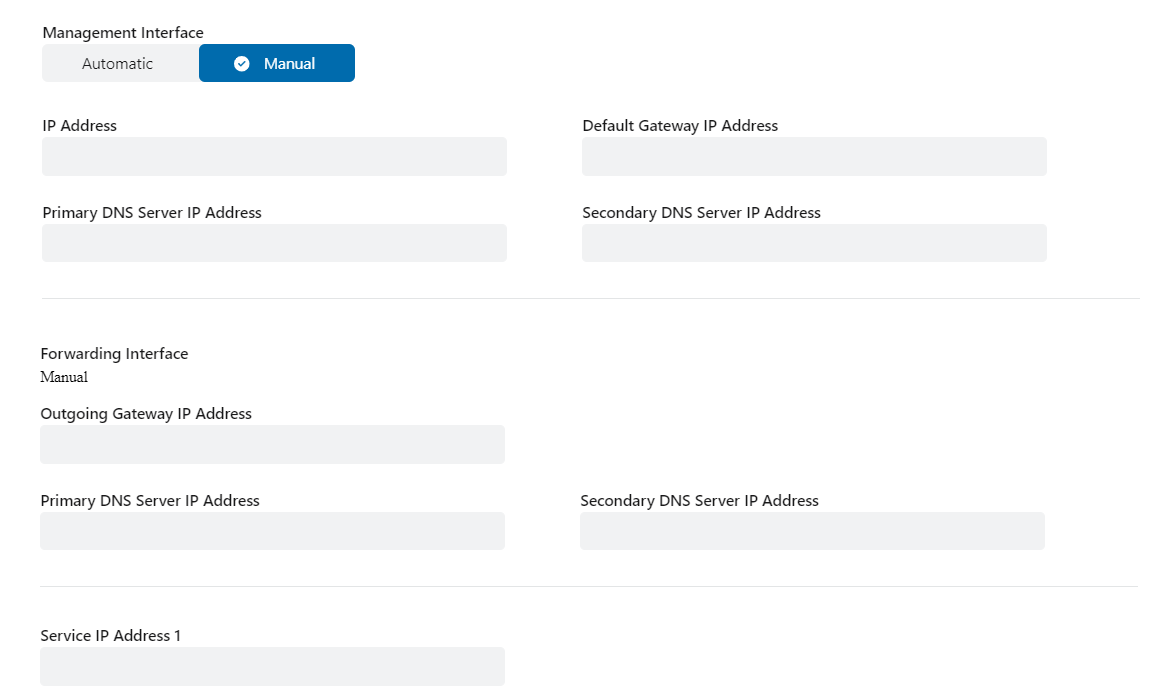
Select Automatic or Manual. If Automatic is selected, all fields are displayed automatically. If Manual is selected, in the following sections:
- Management Interface
Use the Management Interface section to configure the Branch Connector's network interface and operations.
- IP Address: Enter the IP address of the Branch Connector.
- Default Gateway IP Address: Enter the default gateway IP address of the Branch Connector.
- Primary DNS Server IP Address: Enter the IP address of the primary DNS server. This is one of the two DNS servers used for load balancing.
- Secondary DNS Server IP Address: Enter the IP address of the secondary DNS server. This is one of the two DNS servers used for load balancing.
- Forwarding Interface
Use the Forwarding Interface section to configure the Branch Connector's selected forwarding destinations.
If High Availability deployment is enabled:
- Primary DNS Server IP Address: Enter the IP address of the primary DNS server.
- Secondary DNS Server IP Address: Enter the IP address of the secondary DNS server.
- Outgoing Gateway IP Address: Enter the default gateway IP address.
- Service IP Address 1: Enter the primary service IP address.
- Service IP Address 2: Enter the secondary service IP address.
- Load Balancer IP Address: Enter the load balancer IP address.
If High Availability deployment is disabled:
- Primary DNS Server IP Address: Enter the IP address of the primary DNS server.
- Secondary DNS Server IP Address: Enter the IP address of the secondary DNS server.
- Outgoing Gateway IP Address: Enter the default gateway IP address.
- Service IP Address 1: Enter the primary service IP address.
- Management Interface
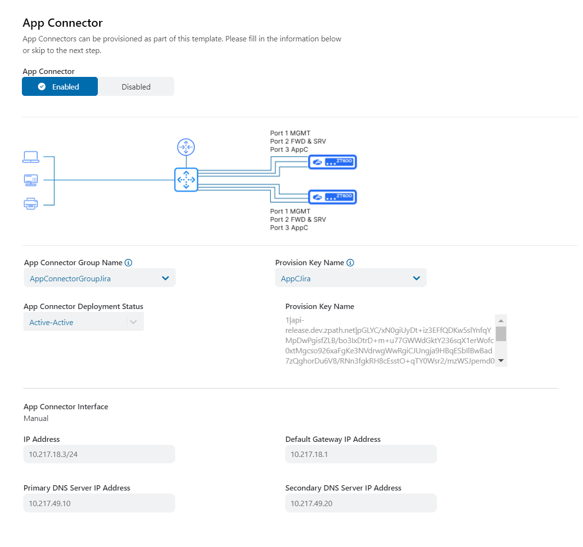
- On the App Connector tab, select Enabled or Disabled. If you enable App Connectors:
- App Connector Group Name: Select your desired App Connector group name.
- Provision Key Name: Select your desired provisioning key name.
- App Connector Deployment Status: This field displays the App Connector deployment status.
App Connector Interface: This field is automatically set to Manual.
- IP Address: Enter the IP address of the App Connector.
- Default Gateway IP Address: Enter the default gateway IP address of the App Connector.
- Primary DNS Server IP Address: Enter the IP address of the primary DNS server. This is one of the two DNS servers used for load balancing.
- Secondary DNS Server IP Address: Enter the IP address of the secondary DNS server. This is one of the two DNS servers used for load balancing.
- On the Review tab, review the values and settings that you entered.
- On the Location tab, select an Existing or New location.
- On the General Information tab:
