Zero Trust Device Segmentation
Deploying on a Zscaler ZTS4000 or ZTS8000
Zero Trust Device Segmentation gateways can be deployed on a Zscaler ZTS4000 or the larger ZTS8000 device. Refer to the hardware specifications table to see the performance differences.
Prerequisites
- Hardware SpecificationsClose
Parameter ZTS4000 ZTS8000 CPU 8C Xeon 16C Xeon Memory 32 GB 64 GB Storage 256 GB 960 GB Ports 4x 1GbE
2x 10GbE4x 1GbE
6x 10GbEForm Factor 1U 1U Other Features RPS RPS Throughput (64KB HTTP) 20 Gbps 40 Gbps Sessions 1M 2M Number of Endpoints 2,000 4,000 - Network InformationClose
Details Value Description Site/Location Name <name> Site or branch name. Device Segmentation Gateway Names <name1>, <name2> Appliance names. Device Segmentation WAN/Uplink IPs <IP1>, <IP2> Device Segmentation upstream/WAN/NIC. Two IP addresses must be in the existing network. Three IP addresses are required for the high-availability deployment. Appliance Default Gateway <IP> Default gateways for the Device Segmentation appliances. DNS Servers <IP1>, <IP2> Enterprise private DNS server IP addresses that must be assigned to devices in the Device Segmentation network. DHCP Servers <IP1>, <IP2> DHCP servers to which DHCP requests are relayed. Ensure that you have a pool assigned for Device Segmentation VLANs. Internet Connectivity hub3.goairgap.com(TCP:1883)wg.goairgap.com(UDP:51820)
Device Segmentation gateways require internet connectivity using these outbound TCP and UDP ports. - Typical Setup

Port Configuration
The ZTS4000 and ZTS8000 have the following ports:
- Serial RJ45 Console Port: You can use PuTTY or similar serial console application to access the Device Segmentation console. Use the following settings for proper serial connection:
- Baud Rate: 115,200
- Data Bits: 8
- Parity: None
- Stop Bits: 1
- Flow Control: Off
- Management Port (enp4s0/enp5s0): Out-of-band management port with a fixed address of 192.168.99.99/24.
- enp18Xs0f0 - 10GbE LAN/WAN Port
- enp18Xs0f1 - 10GbE LAN/WAN Port
- enp2s0f1 - 1GbE LAN/WAN Port
- enp2s0f1 - 1GbE LAN/WAN Port
- enp2s0f2 - 1GbE LAN/WAN Port
- enp2s0f3 - 1GbE LAN/WAN Port
- When used as LAN ports, device-side interfaces connected to the L2 switch via the trunk interface with Device Segmentation-protected VLANs allowed as member ports. The LAN port acts as the default gateway for both Device Segmentation-protected VLANs and devices.
- When used as WAN ports, the upstream interface connects to the L2 switch as an untagged port in the same VLAN as the upstream firewall or L2/L3 switch. All internet-bound or non-Device Segmentation destined traffic is routed to the network/VLAN after the policy check.
- Serial RJ45 Console Port: You can use PuTTY or similar serial console application to access the Device Segmentation console. Use the following settings for proper serial connection:
Configuration
Follow these steps to configure Device Segmentation on a ZTS4000 or ZTS8000:
- Step 1: Connect to a ZTS4000 or ZTS8000.
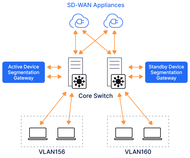
When deployed on a Zscaler ZTS4000 or ZTS8000, Device Segmentation uses two (or six) 10GbE SFP+ ports and four 1GbE RJ45 ports. Any two of these can be configured as LAN (device-side) and WAN (firewall-/router-side) ports.
Connect a laptop to the management port of the Device Segmentation appliance over the RJ45 cable. Configure your laptop’s Ethernet interface with a static IP address in the subnet of 192.168.99.0/24 (e.g., 192.168.99.10).Log in to the Device Segmentation gateway over SSH using the default management IP address and credentials.
You can also connect to the Device Segmentation gateway appliance over the serial RJ45 console port.
- In the gateway command line interface, configure the LAN and WAN ports. Select
1to configure the Device Segmentation gateway and1to configure the network. Review this recording for more information. - Select the LAN and WAN interface from the available options.
- Step 2: Configure the WAN port.
Zscaler recommends that you connect the WAN port group to the network and ensure internet connectivity is active.
Connect the switchport on the WAN side to the untagged or access port and refer to the following Cisco configuration. In this example, the switchport (Te1/1/5) connecting to the WAN side of Device Segmentation is part of the VLAN445 and is configured as an access port.
interface TenGigabitEthernet1/1/55 switchport access vlan 445 switchport mode access- The WAN port is configured with the static address or the DHCP. Virtual IP address is a floating IP address shared across both Device Segmentation gateways when configured in the high availability pair. Review this recording where enp182s0f0 and enp182s0f1 are 10GbE interfaces and configured as a LAN/WAN interface.
- Device Segmentation gateways communicate with various AWS public cloud services such as RDS, ALB, and Elastic over the WAN uplink. These connections can be aggregated into a single outgoing connection via Device Segmentation-hosted forward proxy (e.g.,
hub3.goairgap.com) on TCP port 1883. To configure this proxy setting, select option2in the Configure Gateway menu of the gateway command line interface. - After configuring the IP address and proxy, and establishing internet connectivity for the Device Segmentation gateway, a 6-digit code displays in the gateway command line interface.
- Step 3: Activate Device Segmentation gateways.
Device Segmentation gateway configuration, policy management, logging, and reporting are managed via the SaaS-based Device Segmentation Admin Portal.
To activate the Device Segmentation gateway:
- Go to Networking > Gateways.
Click Add Gateway.
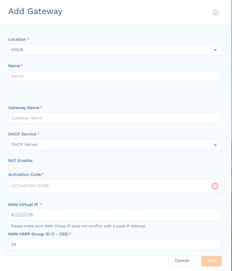
In the Add Gateway panel, complete the following information:
- Location: Select the location for this Device Segmentation gateway, or select Add New Location.
- Name: (Optional) If adding a new location, enter a name for the location.
- Gateway Name: Enter a name for the Device Segmentation gateway.
- DHCP Service: Select DHCP Server or DHCP Relay, based on whether the Device Segmentation gateway is a DHCP server or relay to your existing DHCP server.
- NAT Enable: (Optional) Select this checkbox if your Device Segmentation gateway uses NAT to route all the traffic leaving the Device Segmentation appliance toward the non-Device Segmentation network.
- Activation Code: Enter the code you received when you configured the WAN port. It can take 5 to 10 minutes to activate and provision the appropriate microservices.
- WAN Virtual IP: Enter the floating IP address to be used between two Device Segmentation gateways.
- WAN VRRP Group ID (1 - 255): Enter a number between 1–255 to uniquely identify the WAN router.
- Click Add.
This recording shows the gateway activation process.
- To deploy the Device Segmentation gateway's high-availability pair, configure another appliance and activate it as a standby gateway using the following steps:
- On the Gateway page, click the Gear icon for the gateway that you want to make a standby.
- Select Add Standby Gateway from the menu.
- Provide the standby gateway name, 6-digit code from the newly installed VM, and WAN virtual IP address and group ID number as described in the previous step.
- Click Add.
- Step 4: Configure Device Segmentation gateway LAN.
A single cluster of Device Segmentation gateways can be deployed to protect multiple VLANs. To process multiple VLANs, the switchport connecting to the LAN-side interface of the Device Segmentation gateway must be configured as a trunk port, and it must allow the VLANs that need to be protected by Device Segmentation.
The following is a sample Cisco configuration of a switchport connecting to the LAN side of Device Segmentation gateways. In this example, Te1/1/4 is connected to the LAN side, is configured with trunk, and allows VLAN 226 and VLAN 227.
Closeinterface TenGigabitEthernet1/1/4 switchport trunk allowed vlan 226,227 switchport mode trunk - Step 5: Configure VLAN.
Device Segmentation deployment is not complete until the VLAN to be protected is enabled in the Device Segmentation Admin Portal. Ensure that a LAN port is connected to the switch and that it is in the same VLAN as the devices (broadcast packets from the devices must reach the LAN port). This section describes how to configure Device Segmentation to receive traffic from VLAN 226 and VLAN 227 and protect devices connected to those VLANs.
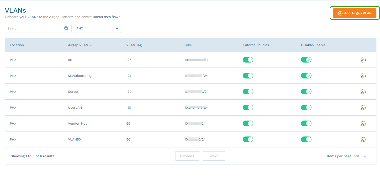
- Go to Networking > VLANs.
Select the site where the Device Segmentation-protected VLAN is configured, and click Add VLAN.
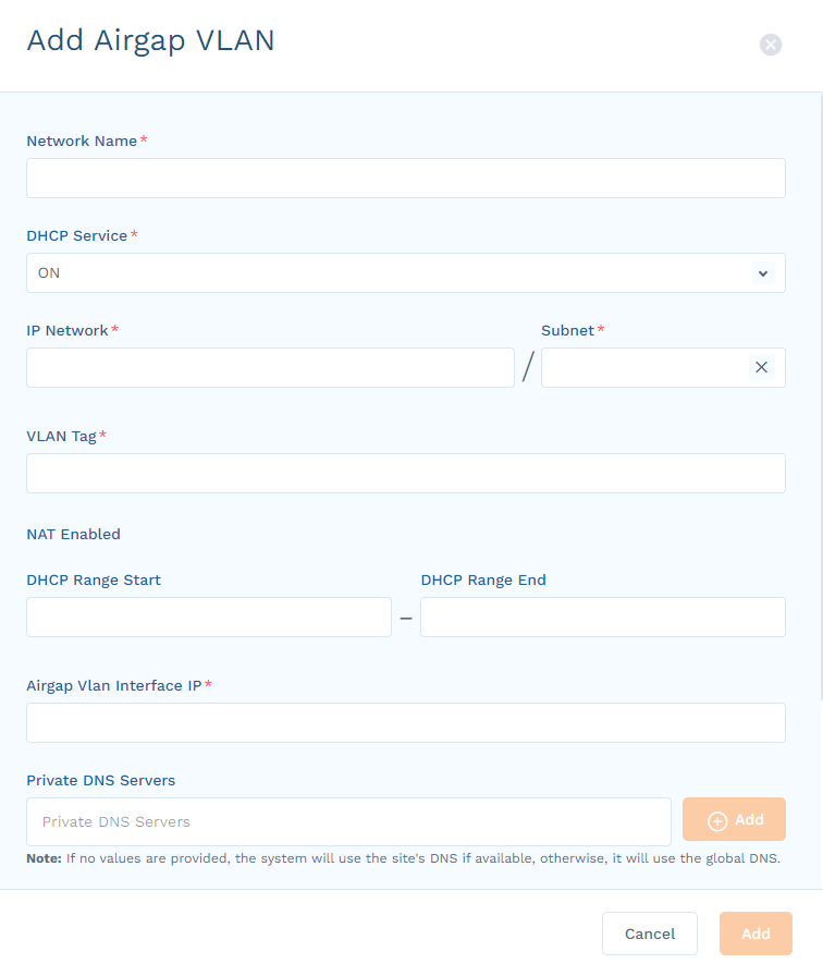
In the Add VLAN panel, complete the information for this VLAN. For an untagged port, enter
1in the VLAN Tag field.If you are using an existing production VLAN, make sure that the default gateway IP address is the same as the existing Switch Virtual Interface (SVI) address for that VLAN.
This recording shows how to add a VLAN.
Log in to your existing L2/L3 switch, router, or firewall, and shut down the SVI/VLAN interface. Add a return route for VLAN with Device Segmentation WAN Virtual IP address as a next hop. Here are sample Cisco commands (for VLAN 226 with subnet mask 10.16.226.0/24):
#conf t
#int vlan 226
#shutdown
#exit
#ip route 10.16.226.0 255.255.255.0 < airgap-wan-vip >
Turn on the VLAN in the Device Segmentation Admin Portal.
By default, the VLANs are created in the staged state. Each VLAN must be enabled to configure it into the Device Segmentation gateways.
The DHCP Service option provides DHCP service ON/OFF and non-airgapped options:
- DHCP Service ON: The Device Segmentation gateway assigns the IP address and
/32net mask and ringfences the endpoints in the VLAN. - DHCP Service OFF: The Device Segmentation gateway acts as a DHCP relay and modifies the DHCP response to
/32net mask and ringfences all the endpoints in the VLAN. - Non-Airgapped: The Device Segmentation gateway assigns the net mask as per the default configured network subnet mask or network mask received from the DHCP servers. It does not ringfence the endpoints. However, the admin can still create segmentation policies based on network and group-level policies.


